This is Photoshop’s version of Lorem Ipsn gravida nibh vel velit auctor aliquet.Aenean sollicitudin, lorem quis bibendum auci. Proin gravida nibh vel veliau ctor aliquenean.

FOLLOW ME ON INSTAGRAM

+01145928421
mymail@gmail.com

MVCS – Iontophoresis

Add to Wishlist Remove from Wishlist

Iontophoresis Amplifier

  • Apply charged substances with high temporatol and spatial precision
  • Target single synaptic boutons – local resolution ~1 µm³
  • High voltage pulses in the sub millisecond range – fastest iontophoretic system on the market
  • Avoid leaking of substances using the hold/retain current settings
  • ±45V or ±150V voltage range with high precision current pump
  • Balance channel with automatic counter-current application to avoid charging of specimen
  • Control the MVCS with any data acquisition system

Features

  • One or two channel versions (upgrade possible)
  • Time resolution: down to 100 µs
  • Spatial resolution: down to 1 µm
  • Simulation of synaptic events, suitable for receptor density mapping
  • Automated balancing of iontophoretic current (option)
  • Currents from tens of pA up to µA
  • High voltage, high speed current source
  • Automated electrode resistance test

Choosing a model

Fast or slow

The fast systems comes with a headstage for each channel. This allows to integrate a capacitance compensation circuitry and resistance measurement. If you need application pulses in the range of a few ms or even below for very focal application, this is the system of choice.

The slower system doesn’t have headstages and capacitance compensation. It is suitable when timing is not an issue (e.g. bulk loading).


Balance channel

The balance channel injects the same amount of current into the sample as the application channel(s) – with opposite polarity. This way the overall charge of the sample remains unchanged. This is especially useful, if parallel recordings are performed, where DC shifts would impair the measurement (e.g. patch clamp).


45 V or 150 V

For 98% of the experiment the 45 V system is fully sufficient. The 150 V system should only be used, if large current are necessary and even possible. Remember that even npi’s instruments can’t cheat Ohm’s law.

Example: 150 V into a 1 MΩ electrode will generate a current of 150 µA.

MVCS Models

Ordering

Part No. Description
MVCS-01-45 MVCS-01-45V 19″ Iontophoresis System
MVCS-01C-45 MVCS-01C-45V 19″ Iontophoresis System (with balance)
MVCS-01U-45 2nd Channel Upgrade f. MVCS-01-45 System (19″)
MVCC-U-45 Balance Upgrade f. MVCS-45 System (19″)
MVCS-02-45 MVCS-02-45V 19″ Iontophoresis System
MVCS-02C-45 MVCS-02C-45V 19″ Iontophoresis System (with balance)
MVCS-01-150 MVCS-01-150V 19″ Iontophoresis System
MVCS-01C-150 MVCS-01-C-150V 19″ Iontophoresis System (with balance)
MVCS-01U-150 2nd Channel Upgrade f. MVCS-01-150 System (19″)
MVCC-U-150 Balance Upgrade f. MVCS-150 System (19″)
MVCS-02-150 MVCS-02-150V 19″ Iontophoresis System
MVCS-02C-150 MVCS-02-C-150V 19″ Iontophoresis System (with balance)
MVCS-C-01-45 MVCS-C-01-45V 19″ Iontophoresis System
MVCS-C-01C-45 MVCS-C-01C-45V 19″ Iontophoresis System (with balance)
MVCS-C-01U-45 2nd Channel Upgrade f. MVCS-C-01C-45
MVCC-C-U-45 Balance Upgrade f. MVCS-C-45 System (19″)
MVCS-C-02-45 MVCS-C-02-45V 19″ Iontophoresis System
MVCS-C-02C-45 MVCS-C-02C-45V 19″ Iontophoresis System (with balance)
MVCS-C-01-150 MVCS-C-01-150V 19″ Iontophoresis System
MVCS-C-01C-150 MVCS-C-01-C-150V 19″ Iontophoresis System (with balance)
MVCS-C-01U-150 2nd Channel Upgrade f. MVCS-C-01C-150 System (19″)
MVCC-C-U-150 Balance Upgrade f. MVCS-C-150 System (19″)
MVCS-C-02-150 MVCS-C-02-150V 19″ Iontophoresis System
MVCS-C-02C-150 MVCS-C-02-C-150V 19″ Iontophoresis System (with balance)
MVCS-01M-45 MVCS-01M-45V Module for EPMS-H
MVCS-01M-150 MVCS-01M-150V Module for EPMS-H
MVCS-02M-45 MVCS-02M-45V Module for EPMS-H
MVCS-02M-150 MVCS-02M-150V Module for EPMS-H
MVCC-M-45 Balance Module f. MVCS-45 System (EPMS-H)
MVCC-M-150 Balance Module f. MVCS-150 System (EPMS-H)
MVCS-C-01M-45 MVCS-C-01M-45V Module for EPMS-H
MVCS-C-01M-150 MVCS-C-01M-150 V Module for EPMS-H
MVCS-C-02M-45 MVCS-C-02M-45V Module for EPMS-H
MVCS-C-02M-150 MVCS-C-02M-150V Module for EPMS-H
MVCC-C-M-45 Balance Module f. MVCS-C-45 System (EPMS-H)
MVCC-C-M-150 Balance Module f. MVCS-C-150 System (EPMS-H)
MVCS-HS-150 Headstage for MVCS-150 Systems
MVCS-HS-45 Headstage for MVCS-45 Systems
MVCS-EH Standard Micro Electrode Holder

Technical Data

MODE of operation: set with two toggle switches, EJECT / RETAIN / AUTO switch enables manual or TTL
controlled operation
SET / OPERATE switch connects automatically electrode outputs to an internally grounded load, to make possible well defined presetting (SET position)
COMPENSATE / OFF / EXTERN switch (balance unit), selects compensation signal or connects
balance module to external signal source (additional channel).
HEADSTAGES Size (approx.): Standard 70x30x25 mm, holding bar diameter 8 mm, length 150 mm (±15 V, ±45 V), optional: 100x50x20 mm (± 150V) or 225x40x60mm (± 225V).
Electrode connector: BNC connector, (headstage with driven shield also available).
Ground connector: 2.4 mm connector.
Electrode output: floating current source, output impedance >1012 Ω
ELECTRODE RESISTANCE TEST 1 mV / MΩ at the voltage monitor Vel / 10, obtained by application of square current pulses,
±10 nA from built-in pulse generator.
EJECT ten-turn control, switch selected range max. 1 µA / 100 nA.
RETAIN ten-turn control, max. 100 nA.
CAPACITY COMPENSATION range 0 ­ 30 pF, ten-turn control.
MAXIMUM CURRENT 150 nA (±15 V), 450 nA (±45 V standard voltage), 1.5 µA (±150 V) into 100 MΩ load. Other ranges available on request.
OUTPUT CURRENT POLARITY:
selected by INVERTED / NORMAL toggle switch.
BALANCE OUTPUT (MVCS-X-02C-45, MVCC):
inverted sum of all currents, sensitivity 1 µA / V, for connecting external balance module.
TTL INPUT (AUTO mode): LO = RETAIN, HI = EJECT, isolated, Rin > 5 kΩ
ANALOG INPUT sensitivity 100 nA / V, Rin > 100 kΩ, range ±10 V.
CURRENT MONITOR sensitivity 100 nA / V, Rout = 250 Ω, not isolated.
VOLTAGE MONITOR Vel / 10, Rout = 250 Ω, not isolated.
DISPLAY current XXXX nA, balance current XX.XX µA, voltage XXX.X V, REL XXXX MΩ,
separate displays for each channel, displayed value is set by a three position toggle switch.
OVER LEDs:
activated 10 % below maximum current.
POWER REQUIREMENTS 115 / 230 V AC, 45 – 60 W.
DIMENSIONS 19″ cabinet, 19“ (483 mm), x 10″ (250 mm) x 3.5″ (88 mm).

Downloads

Manual MVCS manual
Brochure Drug Application

ABOUT

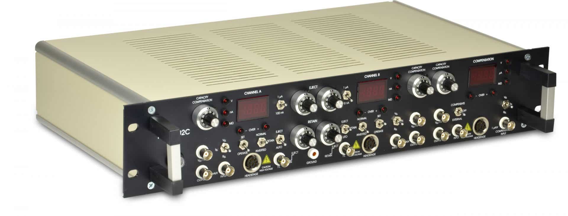
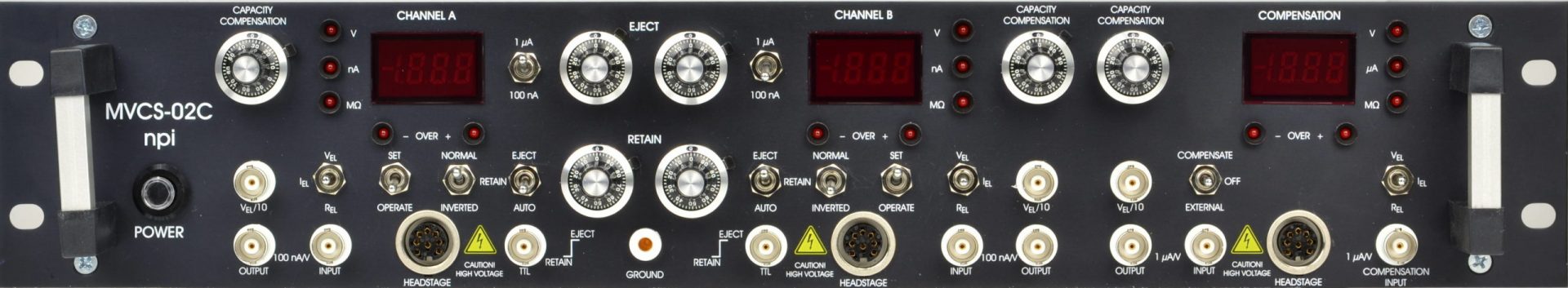
In principle, MVCS systems are available as:

  • A very fast (less than 1 ms) version with capacity compensation and electrode resistance test
  • A slower version without capacity compensation and electrode resistance test

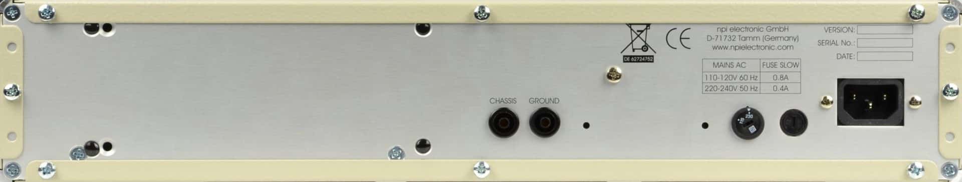
Fast systems (MVCS-C-02C) are delivered with headstages, ground connector, a power cord and a user manual.

Slower systems (MVCS-02C) are delivered with connectors for electrode connection and ground, a power cord and a user manual (without headstages).

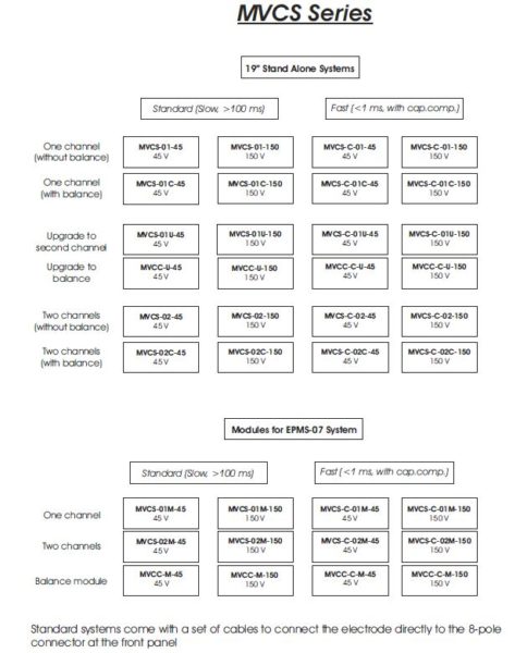
Standard voltage ranges are ±45 V or ±150 V. Other ranges are available on request.

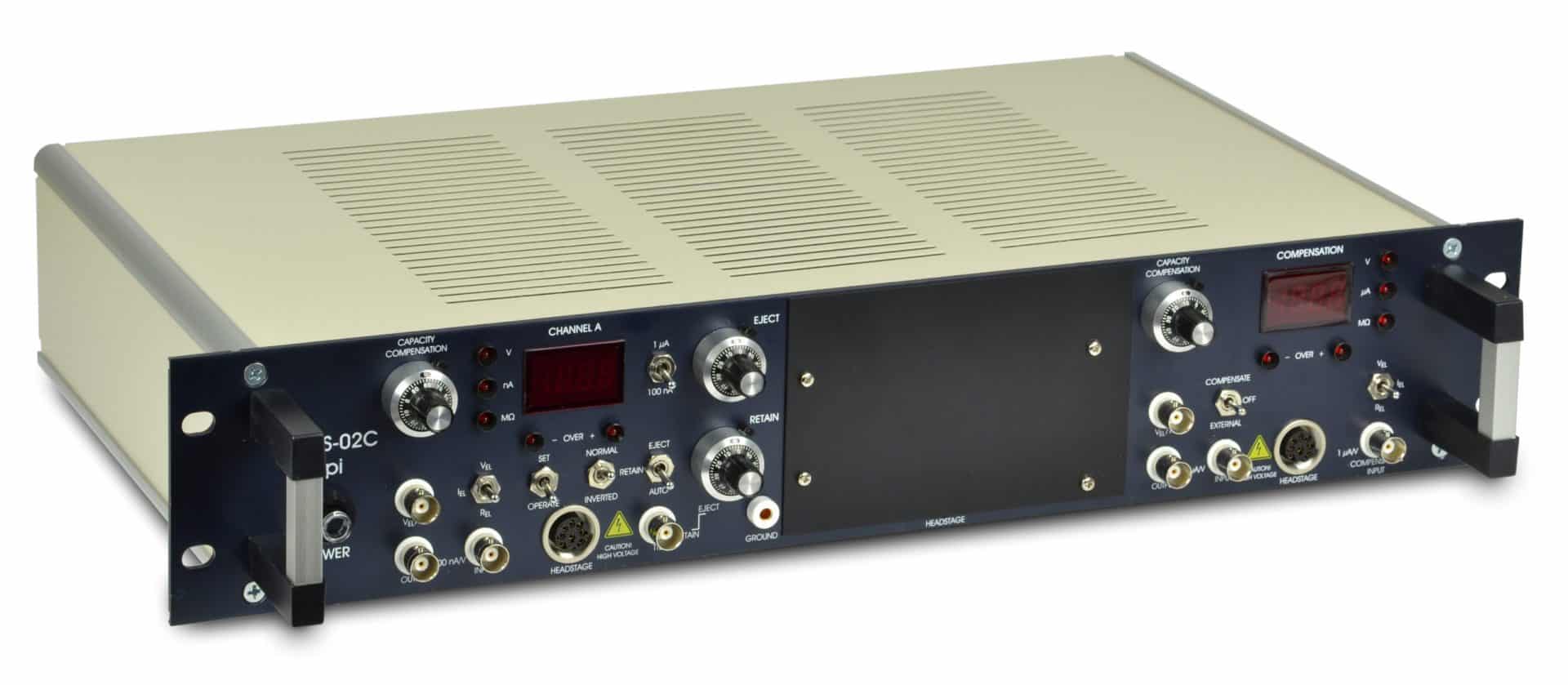
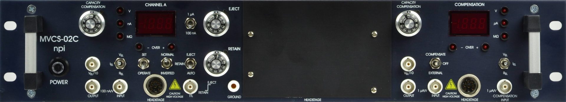
NOTE: All MVCS systems are also available as one-channel versions and one-channel versions can be ugraded to two channels. Furthermore, all version can also be ordered without a balance channel.
Please contact npi electronic or your distributor for details.

Look at the “MVCS Models” tab below for all options. Customized configurations are possible, please contact npi electronic.

The MVCS is also available as module for the EPMS-07 system.

Features

Features

  • One or two channel versions (upgrade possible)
  • Time resolution: down to 100 µs
  • Spatial resolution: down to 1 µm
  • Simulation of synaptic events, suitable for receptor density mapping
  • Automated balancing of iontophoretic current (option)
  • Currents from tens of pA up to µA
  • High voltage, high speed current source
  • Automated electrode resistance test

Choosing a model

Choosing a model

Fast or slow

The fast systems comes with a headstage for each channel. This allows to integrate a capacitance compensation circuitry and resistance measurement. If you need application pulses in the range of a few ms or even below for very focal application, this is the system of choice.

The slower system doesn’t have headstages and capacitance compensation. It is suitable when timing is not an issue (e.g. bulk loading).


Balance channel

The balance channel injects the same amount of current into the sample as the application channel(s) – with opposite polarity. This way the overall charge of the sample remains unchanged. This is especially useful, if parallel recordings are performed, where DC shifts would impair the measurement (e.g. patch clamp).


45 V or 150 V

For 98% of the experiment the 45 V system is fully sufficient. The 150 V system should only be used, if large current are necessary and even possible. Remember that even npi’s instruments can’t cheat Ohm’s law.

Example: 150 V into a 1 MΩ electrode will generate a current of 150 µA.

MVCS Models

MVCS Models

Ordering

Ordering

Part No. Description
MVCS-01-45 MVCS-01-45V 19″ Iontophoresis System
MVCS-01C-45 MVCS-01C-45V 19″ Iontophoresis System (with balance)
MVCS-01U-45 2nd Channel Upgrade f. MVCS-01-45 System (19″)
MVCC-U-45 Balance Upgrade f. MVCS-45 System (19″)
MVCS-02-45 MVCS-02-45V 19″ Iontophoresis System
MVCS-02C-45 MVCS-02C-45V 19″ Iontophoresis System (with balance)
MVCS-01-150 MVCS-01-150V 19″ Iontophoresis System
MVCS-01C-150 MVCS-01-C-150V 19″ Iontophoresis System (with balance)
MVCS-01U-150 2nd Channel Upgrade f. MVCS-01-150 System (19″)
MVCC-U-150 Balance Upgrade f. MVCS-150 System (19″)
MVCS-02-150 MVCS-02-150V 19″ Iontophoresis System
MVCS-02C-150 MVCS-02-C-150V 19″ Iontophoresis System (with balance)
MVCS-C-01-45 MVCS-C-01-45V 19″ Iontophoresis System
MVCS-C-01C-45 MVCS-C-01C-45V 19″ Iontophoresis System (with balance)
MVCS-C-01U-45 2nd Channel Upgrade f. MVCS-C-01C-45
MVCC-C-U-45 Balance Upgrade f. MVCS-C-45 System (19″)
MVCS-C-02-45 MVCS-C-02-45V 19″ Iontophoresis System
MVCS-C-02C-45 MVCS-C-02C-45V 19″ Iontophoresis System (with balance)
MVCS-C-01-150 MVCS-C-01-150V 19″ Iontophoresis System
MVCS-C-01C-150 MVCS-C-01-C-150V 19″ Iontophoresis System (with balance)
MVCS-C-01U-150 2nd Channel Upgrade f. MVCS-C-01C-150 System (19″)
MVCC-C-U-150 Balance Upgrade f. MVCS-C-150 System (19″)
MVCS-C-02-150 MVCS-C-02-150V 19″ Iontophoresis System
MVCS-C-02C-150 MVCS-C-02-C-150V 19″ Iontophoresis System (with balance)
MVCS-01M-45 MVCS-01M-45V Module for EPMS-H
MVCS-01M-150 MVCS-01M-150V Module for EPMS-H
MVCS-02M-45 MVCS-02M-45V Module for EPMS-H
MVCS-02M-150 MVCS-02M-150V Module for EPMS-H
MVCC-M-45 Balance Module f. MVCS-45 System (EPMS-H)
MVCC-M-150 Balance Module f. MVCS-150 System (EPMS-H)
MVCS-C-01M-45 MVCS-C-01M-45V Module for EPMS-H
MVCS-C-01M-150 MVCS-C-01M-150 V Module for EPMS-H
MVCS-C-02M-45 MVCS-C-02M-45V Module for EPMS-H
MVCS-C-02M-150 MVCS-C-02M-150V Module for EPMS-H
MVCC-C-M-45 Balance Module f. MVCS-C-45 System (EPMS-H)
MVCC-C-M-150 Balance Module f. MVCS-C-150 System (EPMS-H)
MVCS-HS-150 Headstage for MVCS-150 Systems
MVCS-HS-45 Headstage for MVCS-45 Systems
MVCS-EH Standard Micro Electrode Holder

Technical Data

Technical Data

MODE of operation: set with two toggle switches, EJECT / RETAIN / AUTO switch enables manual or TTL
controlled operation
SET / OPERATE switch connects automatically electrode outputs to an internally grounded load, to make possible well defined presetting (SET position)
COMPENSATE / OFF / EXTERN switch (balance unit), selects compensation signal or connects
balance module to external signal source (additional channel).
HEADSTAGES Size (approx.): Standard 70x30x25 mm, holding bar diameter 8 mm, length 150 mm (±15 V, ±45 V), optional: 100x50x20 mm (± 150V) or 225x40x60mm (± 225V).
Electrode connector: BNC connector, (headstage with driven shield also available).
Ground connector: 2.4 mm connector.
Electrode output: floating current source, output impedance >1012 Ω
ELECTRODE RESISTANCE TEST 1 mV / MΩ at the voltage monitor Vel / 10, obtained by application of square current pulses,
±10 nA from built-in pulse generator.
EJECT ten-turn control, switch selected range max. 1 µA / 100 nA.
RETAIN ten-turn control, max. 100 nA.
CAPACITY COMPENSATION range 0 ­ 30 pF, ten-turn control.
MAXIMUM CURRENT 150 nA (±15 V), 450 nA (±45 V standard voltage), 1.5 µA (±150 V) into 100 MΩ load. Other ranges available on request.
OUTPUT CURRENT POLARITY:
selected by INVERTED / NORMAL toggle switch.
BALANCE OUTPUT (MVCS-X-02C-45, MVCC):
inverted sum of all currents, sensitivity 1 µA / V, for connecting external balance module.
TTL INPUT (AUTO mode): LO = RETAIN, HI = EJECT, isolated, Rin > 5 kΩ
ANALOG INPUT sensitivity 100 nA / V, Rin > 100 kΩ, range ±10 V.
CURRENT MONITOR sensitivity 100 nA / V, Rout = 250 Ω, not isolated.
VOLTAGE MONITOR Vel / 10, Rout = 250 Ω, not isolated.
DISPLAY current XXXX nA, balance current XX.XX µA, voltage XXX.X V, REL XXXX MΩ,
separate displays for each channel, displayed value is set by a three position toggle switch.
OVER LEDs:
activated 10 % below maximum current.
POWER REQUIREMENTS 115 / 230 V AC, 45 – 60 W.
DIMENSIONS 19″ cabinet, 19“ (483 mm), x 10″ (250 mm) x 3.5″ (88 mm).

Downloads

Downloads

Manual MVCS manual
Brochure Drug Application