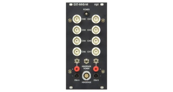
| HEADSTAGES |
Size (approx.): Standard 65x25x25 mm, holding bar diameter 8 mm, length 150 mm, mounting plate or dovetail on request,
Electrode connector: BNC connector,
Ground connector: 2.4 mm connector.
Electrode output: floating current source, output impedance >1012 Ω. |
| MAXIMUM CURRENT |
±450 nA (±45 V) or ±1.5 µA (±150 V) into 100 MΩ load. Other ranges available on request. |
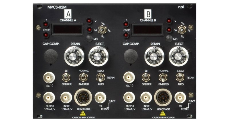
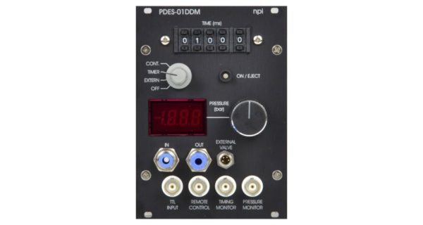
| DISPLAY |
current XXXX nA, voltage XXX.X V, REL XXXX MΩ,
separate displays for each channel, displayed value is set by a three position toggle switch. |
| OVER LEDs |
activated 10 % below maximum current. |
| EJECT |
ten-turn control, switch selected range max. 1 µA / 100 nA. |
| RETAIN |
ten-turn control, max. 100 nA. |
| CAPACITY COMPENSATION |
range 0 30 pF, ten-turn control. |
| OUTPUT CURRENT POLARITY |
selected by INVERTED / NORMAL toggle switch. |
| MODE of operation |
set with toggle switches,
EJECT / RETAIN / AUTO switch enables manual or TTL controlled operation,
SET / OPERATE switch connects automatically electrode outputs to an internally grounded load, to make possible well defined presetting (SET position), |
| TTL INPUT (AUTO mode) |
LO = RETAIN, HI = EJECT, isolated, Rin > 5 kΩ. |
| ANALOG INPUT |
sensitivity 100 nA / V, Rin > 100 kΩ, range ±10 V. |
| CURRENT MONITOR |
sensitivity 100 nA / V, Rout = 50 Ω, not isolated. |
| VOLTAGE MONITOR |
Vel / 10, Rout = 50 Ω, not isolated. |
| ELECTRODE RESISTANCE TEST |
obtained by application of square current pulses, ±10 nA from built-in pulse generator. |
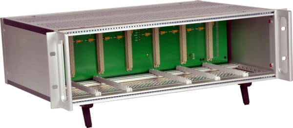
| POWER REQUIREMENTS |
115 / 230 V AC, 45 – 60 W. |