This is Photoshop’s version of Lorem Ipsn gravida nibh vel velit auctor aliquet.Aenean sollicitudin, lorem quis bibendum auci. Proin gravida nibh vel veliau ctor aliquenean.

FOLLOW ME ON INSTAGRAM

+01145928421
mymail@gmail.com

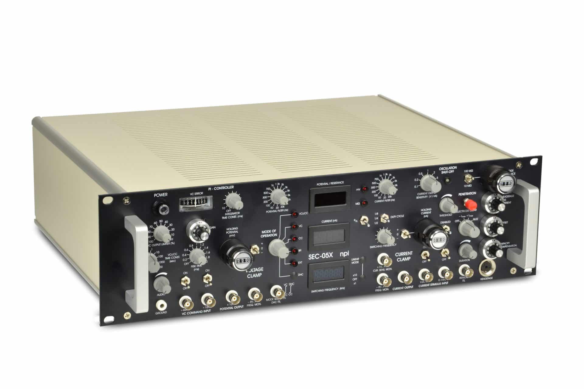
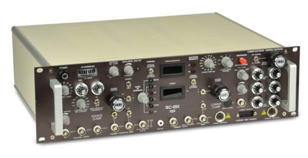
SEC-05X – Single Electrode Clamp

Add to Wishlist Remove from Wishlist

High Quality Single Electrode Voltage Clamp and Current Clamp Amplifier

  • Save money with this simpler version of the SEC-10LX
  • Avoid series resistance induced errors
  • Same performance and speed as the SEC-10LX
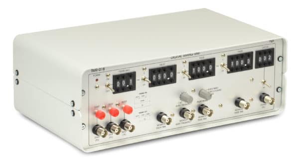
  • Gating unit available as accessory
  • Modular version available: SEC-03M

Features

  • Four modes of operation by default
    • Bridge mode (BR)
    • Current Clamp mode (CC)
    • Voltage Clamp mode (VC)
    • Electrode resistance test mode (REL)
  • Three additional modes optional
    • Voltage Clamp controlled Current Clamp mode (VCcCC)
      Allows Current Clamp experiments at controlled resting potentials
    • Dynamic Hybrid Clamp mode (DHC)
      Allows precise measurement of conductances after action potentials
    • Linear (unswitched) mode (LIN), optional with series resistance compensation
      x1: Allows low-noise recordings of small currents, and approaching the cell and seal formation in VC mode
      x10: Provides 10 times more current in CC and 10 times more voltage in VC mode for non-invasive (juxtacellular) filling of cells
  • Complete compensation of electrode artifacts allowing high (>30 kHz) switching frequencies
  • No series resistance errors
  • Perfect for recording also from coupled cells with two synchronized SEC amplifers (SEC-DUAL)
  • Recordings with sharp microelectrodes or patch pipettes
  • True current clamp in switched and bridge mode
  • Fast switched voltage clamp with proportional-integral (PI) controller
  • Versatile and configurable penetration unit
  • BESSEL filters for current and voltage (16 corner frequencies)
  • Monitors for filters and current output sensitivity
  • Optional Gating Unit GIA-05X (contact us for further details)

Also available as module for the EPMS-07 System.

Ordering

Part No. Description
SEC-05X SEC 05X System
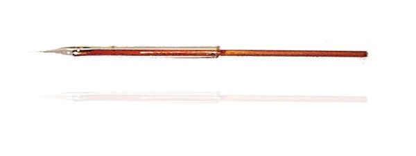
SEC-EH Standard Micro-/Patch Electrode Holder
SEC-EH-SET Electrode Holder Set for SEC Amplifiers
SEC-MOD SEC Cell Model Circuit
SEC-DUAL-05 System for Double Cell Voltage Clamp Recordings (2x SEC-05X)
SEC-PRS Remote Control f. PENETRATION unit
SEC-CON SMB Cable for SEC Headstage
SEC-HS SEC-HS Standard Headstage
SEC-EXT SEC-EXT Headstage for extracellular recordings
SEC-HSD SEC-HSD Headstage with differential input
SEC-HSP SEC-HSP Low-noise Headstage
SEC-MINI Miniature headstage for SEC-series amplifier. Many different configurations available for in-vivo or in-vitro use, housing and cable options. Please contact us for further information and prices.
SEC-H High Voltage Modification of SEC System (surplus)
SEC-SLOW VCcCC Modification of SEC System, Surplus
SEC-LIN SEC with Linear Mode, (CC/VC x1, CC/VC x10 modes), Surplus
SEC-LIN-RS SEC with Linear Mode, (CC/VC x1, CC/VC x10 modes) and Series Res. Comp., Surplus
SEC-DHC Dynamic Hybrid Clamp (DHC) Modification of SEC System, Surplus

Technical Data

MODES of OPERATION R : Electrode resistance test EL
BR: Bridge mode
CC: Current Clamp mode
VC: Voltage Clamp Mode
DHC: Dynamic Hybrid Clamp mode (option)
VCcCC: Voltage Clamp controlled
Current Clamp mode (option)
LIN: Linear mode (x1 and x10)
LIN: Linear mode with series resistance compensation
Mode selection:
rotary switch with six positions (SEC 05X)
four pushbuttons (SEC 10LX)
rotary switch with five positions (SEC 03)
Linear mode with switch
HEADSTAGES Standard headstage(SH), low-noise Headstages(HSP)
operation voltage: ±15 V
size: 100x40x25mm, HSP: 77x37x20mm
headstage enclosure connected to ground
electrode connector: gold plated SMB (SH)
BNC connector (HSP), both with driven shield
ground: 2.4 mm connector or headstage enclosure
input resistance: 1013 Ohms
current range (continuous mode):
150 nA (SH); 15 nA into 100 MOhms (HSP)
CC control: Coarse control for cap. comp.
holding bar (SH): diameter 8 mm, length 10 cm
mounting plate (HSP headstage) 60×50 mm
EXT headstage: 1 mm connectors,
differential high impedance input, gain of ten
cap. comp. for the non-inverting input
high pass filter with six corner frequencies
(1; 3; 10; 30; 100; 300 Hz)
BANDWIDTH AND SPEED OF RESPONSE Full power bandwidth (Re=0): >100 kHz
rise time (10-90%, Re = 100 MOhms) <30 μs
rise time (10-90%, Re = 5 MOhms) <8 μs
Electrode artifact decay (switched modes
10 nA signal) <1 μs (Re = 5 MOhms)
<1.5 μs (Re = 100 MOhms)
cap. comp. tuned with no overshoot
ELECTRODE RESISTANCE TEST 10 mV/MOhm, obtained by application of square
current pulses ±1 nA, display XXX MOhm
OSCILLATION SHUT-OFF Turns off current injection and cap. comp.
indicated by red/green LED,
disabled / off / reset switch
threshold set with linear control (0-1200 mV).
SEC-03: no oscillation shut-off
CELL PENETRATION Overcompensation of cap. comp.,
timer controlled,with remote switch
connected via BNC connector.
Application of DC pulses, variable frequency and
amplitude, timer controlled, with remote switch
connected via BNC connector (SEC-10).
Application of max. continuous DC current, BUZZ,
with push button or remote switch connected via
BNC connector (SEC-05).
No cell penetration unit (SEC-03)
(modular penetration unit available)
SWITCHED MODES PARAMETERS Switching frequency: linear control
1.5 to >50 kHz; display: XX.XX kHz.
duty cycles: 1/2, 1/4, 1/8
selected by toggle switch.
SEC-03: fixed 1/4 duty cycleCURRENT RANGE vs. DUTY CYCLE
1/8 – 15 nA; 1/4 – 30 nA, 1/2 – 60 nA
(standard 15 V headstage)
1/8 – 1.5 nA; 1/4 – 3 nA, 1/2 – 6 nA
(low noise headstage)
SWITCHED MODE OUTPUTS Electrode potential: max. ±15 V,
output impedance 250 Ohms.
switching frequency: TTL (5 V),
output impedance 250 Ohms.
CURRENT OUTPUT Sensitivity: 0.1…10 V/nA in 1-2-5 steps
with lowpass Bessel filter
output impedance 250 Ohms
sensitivity monitor: 1…7 V, 1V/switch position
output impedance 250 Ohms
current display: X.XX nA
SEC-03: fix 0.1V/nA
POTENTIAL OUPUT Sensitivity x10 mV, with lowpass Bessel filter
output impedance 250 Ohms
potential display: XXX mV
AUDIO MONITOR Pitch correlated with potential signal
OUTPUT FILTERS SEC-05: four-pole lowpass Bessel filter with 16 corner frequencies, 20 Hz – 20 kHz
frequency monitor: -8…+7 V, 1 V/switch position
output impedance 250 Ohms.
SEC-10: four-pole lowpass Bessel filter with 16 corner frequencies, 20 Hz – 20 kHz
frequency monitor: -8…+7 V, 1 V/switch position
output impedance 250 Ohms.
SEC-03: unfiltered or 5 kHz, internally adjustable
CURRENT CLAMP Inputs: 1 nA/V, 0.1 nA/V with ON/OFF switches
SEC-03: 1 nA/V
input resistance >100 kOhms
hold: X.XX nA ten-turn digital control, -/0/+ switch
max. 10 nA.
Gated input (SEC-10 systems only): X.XX nA
with +/0/- switch, TTL input (HI >2.5 V, input
resistance 10 kOhm).
BRIDGE balance: XXX MOhms with
ten-turn digital control.
noise (BRIDGE MODE): 400μV pp / pA pp
with 100 MOhms resistance at 10 kHz bandwidth
(internal four-pole Bessel filters)
VOLTAGE CLAMP
Inputs: 10 mV or 40 mV
SEC-03: 10mV
input resistance >100 kOhms
hold: XXX mV, ten-turn digital control
with +/0/- switch, max. 1000 mV
rise time limit: 0-2 ms (SEC-05 / SEC-10 only)
gain: 100 nA/V – 10 μA/V ten-turn linear control
noise (filters set to 10 kHz, SEC-05 / SEC-10)
Potential output: <400 μV pp
current output: <400 pA pp
SPEED of RESPONSE (VC Mode) 1 % settling time: <80 μs for 10 mV step
<800 μs for 50 mV step applied to cell model
(Re= 100 MOhms, Rm= 50 MOhms, Cm= 470 pF
duty cycle = 1/4, switching frequency = 30 kHz
standard headstage)
<400 μs with 1/2 duty cycle.
DIMENSIONS SEC-05 / SEC-10 systems:
19″ (483 mm) wide
14″ (355 mm) deep
5.25″ (132.5 mm) high,
SEC-03 (two slots):
24 HP (121 mm) x 3U (128 mm) x 7 inch (175 mm)

Downloads

Manuals SEC-05X_manual
Brochure SEC Series

ABOUT

SEC series systems are versatile intracellular recording systems. SEC systems are the fastest and most accurate single-electrode current – and voltage – clamp systems available.
These amplifiers are suitable for recordings with high resistance microelectrodes, for tight-seal perforated patch, or whole-cell recording techniques. They also allow intracellular recordings during in vivo voltammetry experiments. Currently, SEC amplifiers are used in vertebrate (rat, mouse, cat, fish etc.) and invertebrate (leech, crab, snail, insect etc.) neurons, muscle cells, other excitable tissue and plant cells.
A significant improvement over other time-sharing amplifiers is that the SEC systems fully compensate the recording microelectrode. This allows single electrode recordings with the same accuracy and speed of response as with the standard two electrode voltage clamp approach.

All systems include four (optionally eight) modes of operation, many automatic functions, protection circuits, versatile I/O signal conditioning units, and digitally controlled operation. All of these features make these amplifiers the ideal research instruments for all electrophysiological investigations using intracellular microelectrodes or suction electrodes (patch pipettes).

The SEC is also available as module for the EPMS-07 System.

All SEC amplifiers are available with LINEAR MODE for low-noise recording of small currents with patch pipettes. It also allows loose-patch or macro-patch recordings, and can be used to approach the cell and form a gigaseal in VC mode.

The linear mode includes now also a switch that enhances the current and voltage range ten times. Therefore, the amplifiers can also be used for juxta-cellular filling of cells with dyes or single cell transfection with DNA.

Existing SEC amplifiers can be upgraded to linear mode. Please contact npi electronic for details.

Features

Features

  • Four modes of operation by default
    • Bridge mode (BR)
    • Current Clamp mode (CC)
    • Voltage Clamp mode (VC)
    • Electrode resistance test mode (REL)
  • Three additional modes optional
    • Voltage Clamp controlled Current Clamp mode (VCcCC)
      Allows Current Clamp experiments at controlled resting potentials
    • Dynamic Hybrid Clamp mode (DHC)
      Allows precise measurement of conductances after action potentials
    • Linear (unswitched) mode (LIN), optional with series resistance compensation
      x1: Allows low-noise recordings of small currents, and approaching the cell and seal formation in VC mode
      x10: Provides 10 times more current in CC and 10 times more voltage in VC mode for non-invasive (juxtacellular) filling of cells
  • Complete compensation of electrode artifacts allowing high (>30 kHz) switching frequencies
  • No series resistance errors
  • Perfect for recording also from coupled cells with two synchronized SEC amplifers (SEC-DUAL)
  • Recordings with sharp microelectrodes or patch pipettes
  • True current clamp in switched and bridge mode
  • Fast switched voltage clamp with proportional-integral (PI) controller
  • Versatile and configurable penetration unit
  • BESSEL filters for current and voltage (16 corner frequencies)
  • Monitors for filters and current output sensitivity
  • Optional Gating Unit GIA-05X (contact us for further details)

Also available as module for the EPMS-07 System.

Ordering

Ordering

Part No. Description
SEC-05X SEC 05X System
SEC-EH Standard Micro-/Patch Electrode Holder
SEC-EH-SET Electrode Holder Set for SEC Amplifiers
SEC-MOD SEC Cell Model Circuit
SEC-DUAL-05 System for Double Cell Voltage Clamp Recordings (2x SEC-05X)
SEC-PRS Remote Control f. PENETRATION unit
SEC-CON SMB Cable for SEC Headstage
SEC-HS SEC-HS Standard Headstage
SEC-EXT SEC-EXT Headstage for extracellular recordings
SEC-HSD SEC-HSD Headstage with differential input
SEC-HSP SEC-HSP Low-noise Headstage
SEC-MINI Miniature headstage for SEC-series amplifier. Many different configurations available for in-vivo or in-vitro use, housing and cable options. Please contact us for further information and prices.
SEC-H High Voltage Modification of SEC System (surplus)
SEC-SLOW VCcCC Modification of SEC System, Surplus
SEC-LIN SEC with Linear Mode, (CC/VC x1, CC/VC x10 modes), Surplus
SEC-LIN-RS SEC with Linear Mode, (CC/VC x1, CC/VC x10 modes) and Series Res. Comp., Surplus
SEC-DHC Dynamic Hybrid Clamp (DHC) Modification of SEC System, Surplus

Technical Data

Technical Data

MODES of OPERATION R : Electrode resistance test EL
BR: Bridge mode
CC: Current Clamp mode
VC: Voltage Clamp Mode
DHC: Dynamic Hybrid Clamp mode (option)
VCcCC: Voltage Clamp controlled
Current Clamp mode (option)
LIN: Linear mode (x1 and x10)
LIN: Linear mode with series resistance compensation
Mode selection:
rotary switch with six positions (SEC 05X)
four pushbuttons (SEC 10LX)
rotary switch with five positions (SEC 03)
Linear mode with switch
HEADSTAGES Standard headstage(SH), low-noise Headstages(HSP)
operation voltage: ±15 V
size: 100x40x25mm, HSP: 77x37x20mm
headstage enclosure connected to ground
electrode connector: gold plated SMB (SH)
BNC connector (HSP), both with driven shield
ground: 2.4 mm connector or headstage enclosure
input resistance: 1013 Ohms
current range (continuous mode):
150 nA (SH); 15 nA into 100 MOhms (HSP)
CC control: Coarse control for cap. comp.
holding bar (SH): diameter 8 mm, length 10 cm
mounting plate (HSP headstage) 60×50 mm
EXT headstage: 1 mm connectors,
differential high impedance input, gain of ten
cap. comp. for the non-inverting input
high pass filter with six corner frequencies
(1; 3; 10; 30; 100; 300 Hz)
BANDWIDTH AND SPEED OF RESPONSE Full power bandwidth (Re=0): >100 kHz
rise time (10-90%, Re = 100 MOhms) <30 μs
rise time (10-90%, Re = 5 MOhms) <8 μs
Electrode artifact decay (switched modes
10 nA signal) <1 μs (Re = 5 MOhms)
<1.5 μs (Re = 100 MOhms)
cap. comp. tuned with no overshoot
ELECTRODE RESISTANCE TEST 10 mV/MOhm, obtained by application of square
current pulses ±1 nA, display XXX MOhm
OSCILLATION SHUT-OFF Turns off current injection and cap. comp.
indicated by red/green LED,
disabled / off / reset switch
threshold set with linear control (0-1200 mV).
SEC-03: no oscillation shut-off
CELL PENETRATION Overcompensation of cap. comp.,
timer controlled,with remote switch
connected via BNC connector.
Application of DC pulses, variable frequency and
amplitude, timer controlled, with remote switch
connected via BNC connector (SEC-10).
Application of max. continuous DC current, BUZZ,
with push button or remote switch connected via
BNC connector (SEC-05).
No cell penetration unit (SEC-03)
(modular penetration unit available)
SWITCHED MODES PARAMETERS Switching frequency: linear control
1.5 to >50 kHz; display: XX.XX kHz.
duty cycles: 1/2, 1/4, 1/8
selected by toggle switch.
SEC-03: fixed 1/4 duty cycleCURRENT RANGE vs. DUTY CYCLE
1/8 – 15 nA; 1/4 – 30 nA, 1/2 – 60 nA
(standard 15 V headstage)
1/8 – 1.5 nA; 1/4 – 3 nA, 1/2 – 6 nA
(low noise headstage)
SWITCHED MODE OUTPUTS Electrode potential: max. ±15 V,
output impedance 250 Ohms.
switching frequency: TTL (5 V),
output impedance 250 Ohms.
CURRENT OUTPUT Sensitivity: 0.1…10 V/nA in 1-2-5 steps
with lowpass Bessel filter
output impedance 250 Ohms
sensitivity monitor: 1…7 V, 1V/switch position
output impedance 250 Ohms
current display: X.XX nA
SEC-03: fix 0.1V/nA
POTENTIAL OUPUT Sensitivity x10 mV, with lowpass Bessel filter
output impedance 250 Ohms
potential display: XXX mV
AUDIO MONITOR Pitch correlated with potential signal
OUTPUT FILTERS SEC-05: four-pole lowpass Bessel filter with 16 corner frequencies, 20 Hz – 20 kHz
frequency monitor: -8…+7 V, 1 V/switch position
output impedance 250 Ohms.
SEC-10: four-pole lowpass Bessel filter with 16 corner frequencies, 20 Hz – 20 kHz
frequency monitor: -8…+7 V, 1 V/switch position
output impedance 250 Ohms.
SEC-03: unfiltered or 5 kHz, internally adjustable
CURRENT CLAMP Inputs: 1 nA/V, 0.1 nA/V with ON/OFF switches
SEC-03: 1 nA/V
input resistance >100 kOhms
hold: X.XX nA ten-turn digital control, -/0/+ switch
max. 10 nA.
Gated input (SEC-10 systems only): X.XX nA
with +/0/- switch, TTL input (HI >2.5 V, input
resistance 10 kOhm).
BRIDGE balance: XXX MOhms with
ten-turn digital control.
noise (BRIDGE MODE): 400μV pp / pA pp
with 100 MOhms resistance at 10 kHz bandwidth
(internal four-pole Bessel filters)
VOLTAGE CLAMP
Inputs: 10 mV or 40 mV
SEC-03: 10mV
input resistance >100 kOhms
hold: XXX mV, ten-turn digital control
with +/0/- switch, max. 1000 mV
rise time limit: 0-2 ms (SEC-05 / SEC-10 only)
gain: 100 nA/V – 10 μA/V ten-turn linear control
noise (filters set to 10 kHz, SEC-05 / SEC-10)
Potential output: <400 μV pp
current output: <400 pA pp
SPEED of RESPONSE (VC Mode) 1 % settling time: <80 μs for 10 mV step
<800 μs for 50 mV step applied to cell model
(Re= 100 MOhms, Rm= 50 MOhms, Cm= 470 pF
duty cycle = 1/4, switching frequency = 30 kHz
standard headstage)
<400 μs with 1/2 duty cycle.
DIMENSIONS SEC-05 / SEC-10 systems:
19″ (483 mm) wide
14″ (355 mm) deep
5.25″ (132.5 mm) high,
SEC-03 (two slots):
24 HP (121 mm) x 3U (128 mm) x 7 inch (175 mm)

Downloads

Downloads

Manuals SEC-05X_manual
Brochure SEC Series