This is Photoshop’s version of Lorem Ipsn gravida nibh vel velit auctor aliquet.Aenean sollicitudin, lorem quis bibendum auci. Proin gravida nibh vel veliau ctor aliquenean.

FOLLOW ME ON INSTAGRAM

+01145928421
mymail@gmail.com

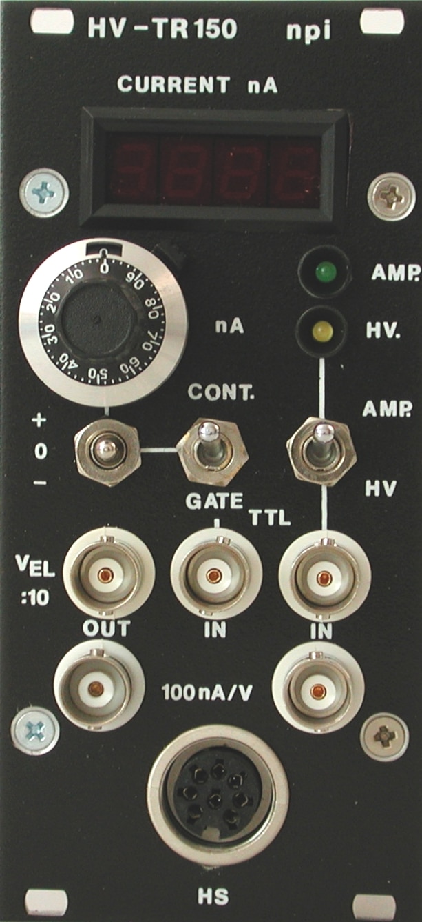
HV-TR150 – Tracer Injection

Add to Wishlist Remove from Wishlist

High Voltage Trace Injection

Features

  • Powerfull current source for iontophoretic application of tracers and dyes
    (max. ±1250 nA in 100 MΩ)
  • Intra or extraclellular recording and injection using the same electrode
  • Works with any intra or extracellular amplifier
  • Digital display for injection current
  • Continuous or gated operation
  • Injection current set by a ten-turn potentiometer, or set by a data acquisition system through an analog input (100 nA / V)
  • Monitors for injection current and electrode voltage

Ordering

Part No. Description
HV-TR150 Tracer Injection Module for EPMS

Technical Data

ELECTRODE OUTPUT floating current source, output impedance >1012 Ω
MAXIMUM CURRENT 1.25 µA into 100 MΩ load
OUTPUT CURRENT POLARITY selected by +/0/- toggle switch
OUTPUT CURRENT AMPLITUDE selected by 10-turn potentiometer or analog inpu
MODES OF OPERATION set by two toggle switches or TTL signal
CONT./GATE switch enables manual or TTL gated operation
AMP./HV. switch connects the recording/application electrode output to amplifier’s headstage or to HV-TR150 current source output
DISPLAY current: XXXX nA
ANALOG INPUT sensitivity 100 nA / V, Rin > 100 kΩ, range ±10 V
CURRENT MONITOR sensitivity 100 nA / V, Rout = 250 Ω, not isolated
VOLTAGE MONITOR VEL / 10, Rout = 250 Ω, not isolated
SIZE front panel 12 HP (60.6 mm) x 3U (128,5 mm), 7” (175 mm) deep
HEADSTAGE SIZE 65x25x25 mm
Holding bar
length: 150 mm; diameter: 8 mm.

Downloads

Manual HV-TR150 manual
Brochures HV-TR150 Brochure
References HV-TR150 Reference List

Features

Features

  • Powerfull current source for iontophoretic application of tracers and dyes
    (max. ±1250 nA in 100 MΩ)
  • Intra or extraclellular recording and injection using the same electrode
  • Works with any intra or extracellular amplifier
  • Digital display for injection current
  • Continuous or gated operation
  • Injection current set by a ten-turn potentiometer, or set by a data acquisition system through an analog input (100 nA / V)
  • Monitors for injection current and electrode voltage

Ordering

Ordering

Part No. Description
HV-TR150 Tracer Injection Module for EPMS

Technical Data

Technical Data

ELECTRODE OUTPUT floating current source, output impedance >1012 Ω
MAXIMUM CURRENT 1.25 µA into 100 MΩ load
OUTPUT CURRENT POLARITY selected by +/0/- toggle switch
OUTPUT CURRENT AMPLITUDE selected by 10-turn potentiometer or analog inpu
MODES OF OPERATION set by two toggle switches or TTL signal
CONT./GATE switch enables manual or TTL gated operation
AMP./HV. switch connects the recording/application electrode output to amplifier’s headstage or to HV-TR150 current source output
DISPLAY current: XXXX nA
ANALOG INPUT sensitivity 100 nA / V, Rin > 100 kΩ, range ±10 V
CURRENT MONITOR sensitivity 100 nA / V, Rout = 250 Ω, not isolated
VOLTAGE MONITOR VEL / 10, Rout = 250 Ω, not isolated
SIZE front panel 12 HP (60.6 mm) x 3U (128,5 mm), 7” (175 mm) deep
HEADSTAGE SIZE 65x25x25 mm
Holding bar
length: 150 mm; diameter: 8 mm.

Downloads

Downloads

Manual HV-TR150 manual
Brochures HV-TR150 Brochure
References HV-TR150 Reference List