Features
- Records extracellularly AC oder DC coupled
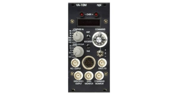
- Allows precise, single cell stimulation with current or voltage
- Suitable for juxtasomal filling of cells with dyes or DNA in loose-patch configuration
- Records and stimulates intracellularly in CC or VC mode
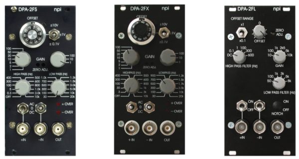
- BRIDGE balance for cancelling the electrode artifact
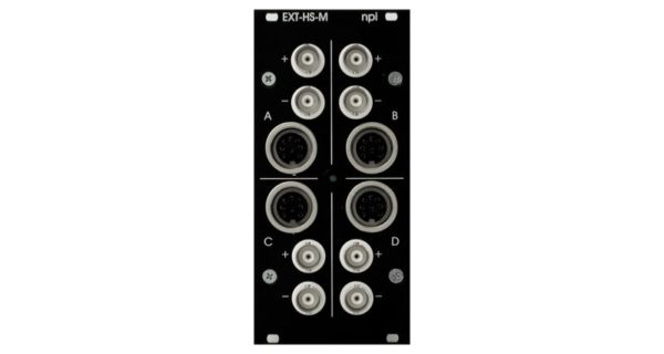
- Available with differential headstage for recordings in vivo
- Suitable for amperometric or voltammetric investigations with carbon fiber electrodes
- Suitable for iontophoresis as well
- 2 Pole High Pass Filter
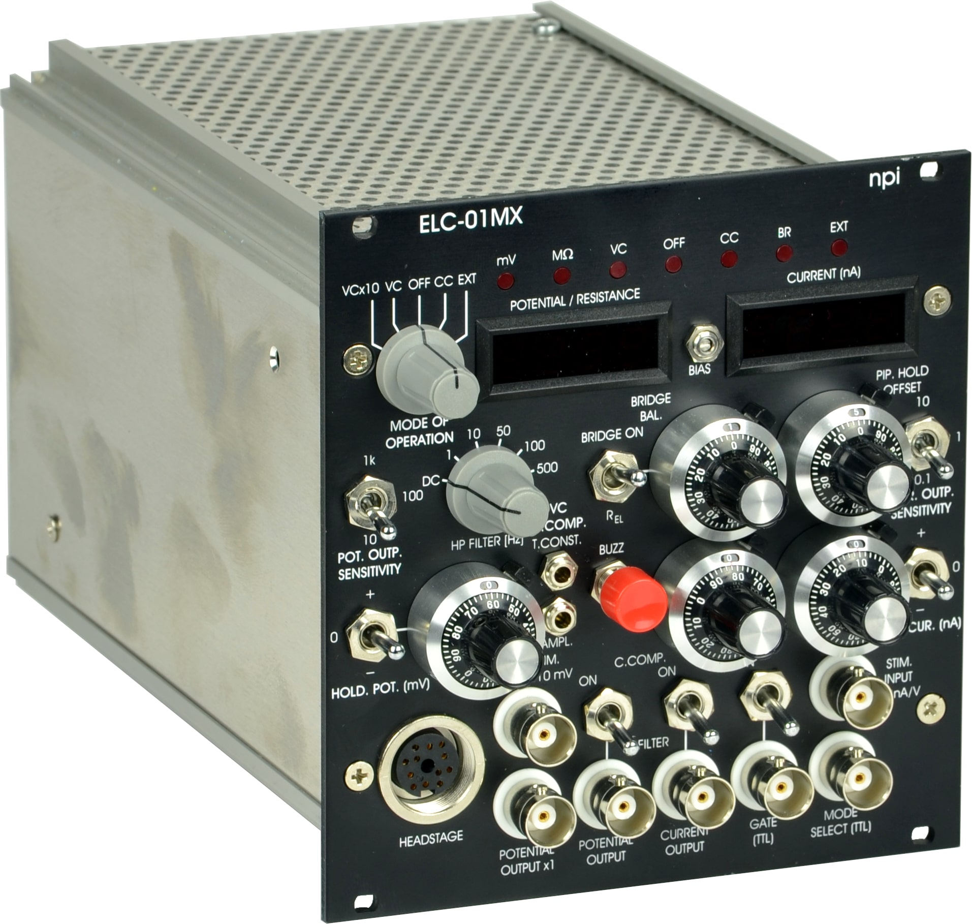
Also available as stand-alone device in 19″ rackmount cabinet.